Linear Tension Geometry
General Information
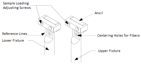
The Linear Tension geometry is used for testing films and fibers in tension. The fiber (cylindrical tension/compression) and film (rectangular tension/compression) fixture share the same type of upper and lower fixtures. A flush-mount set of jaws is provided to hold the films and fibers. Two centered holes on the upper and lower fixture permit the alignment of fibers during loading.
Applicable Environmental Systems
Furnace (ETC)
Recommended Sample Dimensions
To prepare samples that fit within the physical constraints of the geometry, the following are the recommended sample dimensions:
Film Samples
-
L = 35 mm
- T = Up to 1.5 mm
- W = Up to 12.7 mm
Fiber Samples
- L = 35 mm
- R = Up to 0.175 mm
Bulk Samples
(Depends on plate size)
Sample Testing Limits
The suggested dimensions for typical samples allow testing in the recommended range based on the limitations of the size of the test geometry. Note that the sample modulus at test temperature has also a significant effect on the choice of the sample dimensions. A single point test with the desired geometry should be used to fine-tune sample parameters and geometry selection. If too much force is required or the measured strain is significantly lower than the commanded value (which indicates that the transducer compliance may be too large to accurately correct), the sample should be made thinner or narrower to obtain better results. If the sample film or fiber cannot be tested practically by itself, a series of films may be stacked, or fibers may be bundled for testing. In this case, geometries may have to be approximated. Any such slight errors in geometry measurement can produce errors in modulus data, but will not affect temperatures of transitions within the sample.
Installing the Geometry and Loading the Sample
Installing the geometry
Follow these instructions to install the geometry. Refer to the figure below for geometry component identification.
- Use the Raise to loading gap button to raise the stage to the loading position.
-
Install the lower smart swap geometry. Insert the alignment steel shim and tighten the screws of the clamp.
-
Attach the upper geometry and tighten the draw rod. See also Fitting a Geometry on the DHR/AR. Note that the upper clamp is not a smart swap geometry.
-
If this is the first time you are using this geometry, use the Geometry Wizard to configure and define the parameters for this geometry. Otherwise, select the appropriate geometry from the Geometry toolbar on the Experiment tab.
-
Rotate the motor shaft manually to align the upper and lower geometry.With the up and down buttons on the keypad, lower the upper geometry until the steel alignment shim is fully inserted into the anvil of the upper fixture. Tighten the screws of the upper geometry clamp carefully.
- Next, run the axial mapping calibration from the File Manager > Geometries > Calibration. Use the Read Alignment Position to set the alignment position.
- Remove the alignment shim. Bring the upper geometry into the alignment position with the Move to alignment position
 button on the Motor instrument panel. Then click Calibrate to perform the axial mapping.
- When completed, zero the linear test geometry with the Zero Fixture command in the TRIOS Gap Control panel.
- Raise the head to provide room to load the sample.
Preparing the Sample
Cut the sample to a length of 10 to 40 mm. Ensure that the width remains constant along the sample length. Measure the width and thickness or the diameter at 3 positions along the sample and use the average of these values in the calculations.
Loading the Sample (films, fibers)
- Position the upper test fixture to accommodate the desired sample length. From the Motor Instrument panel, click the Move to alignment position button to align the upper test fixture.
- Place the sample between the jaws and tighten the geometry's screw. Using the hex wrench included in the kit, tighten the sample loading bolts to secure the specimen in place. Ensure that the sample is aligned in the geometry by using the scribed lines on the flat plate of the sample geometry jaws for films. Use the alignment holes to center fibers.
- Examine the sample to ensure that it exhibits neither wrinkles nor kinks. If these are present the sample should be remounted.
- Using the stepper motor control buttons on the test station, adjust the stage to provide a very slight tension, as indicated by the NORMAL FORCE meter on the front panel display, or activate axial force control to adjust the static normal force (see also Axial Force Guidelines).
- If desired, properly position the geometry baffles.
Clamping Torque
Follow the guidelines below when preparing the sample to ensure accurate and reliable data:
- Always use the recommended sample size. If the sample does not fit properly in the geometry, erroneous data may result.
- Use the torque screwdriver included with this geometry to adjust the sliding clamps to the proper tightness.
- For each material, experiment to find the clamp torque value that will yield the best results. Under-tightening (or for softer materials, over-tightening) the clamps will result in erratic data.
- After obtaining a good torque value for a specific sample (material and thickness), tighten all subsequent samples to the same value.
Back to top
Coefficient of Thermal Expansion
When testing at other than ambient temperatures, the coefficient of thermal expansion for the Linear Tension geometry compensates for geometry expansion according to the following equation:
With a = Coefficient of thermal expansion [1/°C]
Dt = Change in temperature [°C]
L0 = Original length of sample [mm]
DL = Change in length of sample [mm]
Positive DL indicates increasing of sample length.
Note that when the box is checked in the geometry, the upper fixture is adjusted to compensate for the expansion such that the actual gap remains constant. Refer to Calibrating DHR/AR Geometries to determine the coefficient of Thermal Expansion for the geometry.
Test Procedure Recommendations
- Before starting the test, make sure that the sample is loaded correctly and the test fixture is aligned and locked.
-
If temperature tests are to be performed, use axial force control from the Control panel to stretch/compress the sample before starting the test and insert a Conditioning Options step in the procedure to maintain the axial force control during the test. Use the force tracking mode to ensure that the static force is higher than the dynamic force.
-
For low temperature testing, manually re-tighten the clamps when cooled to temperature before starting the test.
Equations
Rectangular (Film)
Strain Constant

|
Stress Constant

|
Variables
T = Thickness of sample
W = Width of sample
L = Length of sample
|
Cylindrical (Fiber)
Strain Constant
|
Stress Constant

|
Variables
L = Length of sample
Diameter = 2R
|
